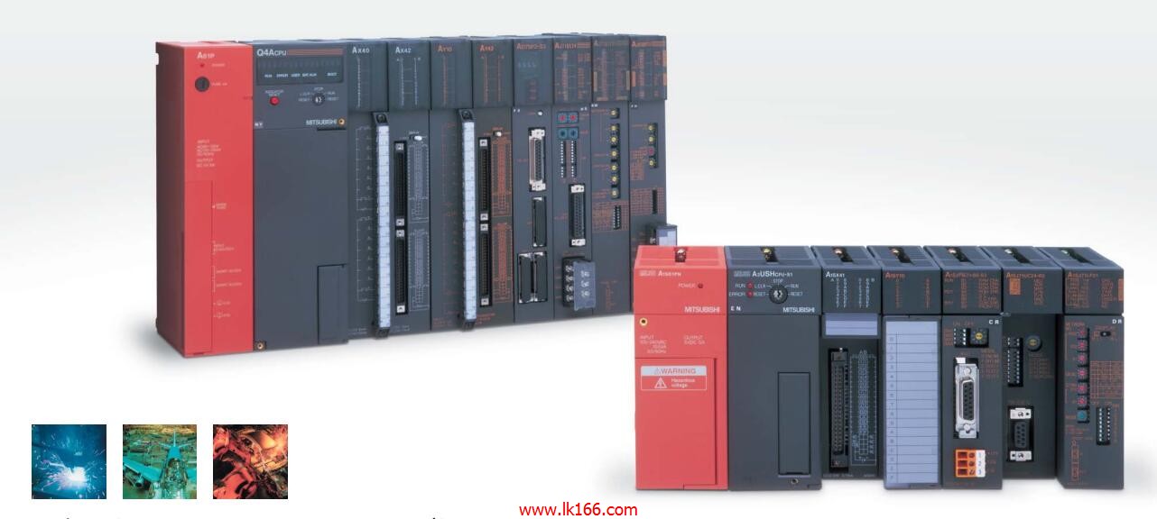
A80BDE-J61BT13 Communication module MITSUBISHI A80BDE-J61BT13

Axis of control: 2.
A1SD71-S2 is a linear interpolation of the pulse sequence output type positioning control module,
The stepper motor is suitable for the servo motor.
The fastest positioning speed up to 200Kpps, positioning range 1-16252928 pulse.
According to the specific application setting positioning unit,
If the number of pulses, mm, inches or degreees, but also to provide compensation to improve the positioning accuracy A80BDE-J61BT13. Output type: transistor output, drain type.
Output points: 8 points A80BDE-J61BT13.
OFF leakage current: 0.1mA.
Output protection function: No.
Rated load voltage / current: DC12V/DC24V/0.5A.
External connection: 1 wire.
According to the external connection mode and the external equipment input and output specifications,
Choose from a rich product lineup A80BDE-J61BT13.
Finger protection through the upper part of the terminal,
The human body will not be exposed to live parts,
Therefore, the terminal station type remote I/O module can be directly mounted to the machine tool.
Output type: transistor output, source.
Output points: 32 points MITSUBISHI A80BDE-J61BT13.
OFF leakage current: 0.1mA.
Output protection function: No.
Rated load voltage / current: DC12V/DC24V/0.5A.
External connection: 1 wire.
According to the external connection mode and the external equipment input and output specifications,
Choose from a rich product lineup MITSUBISHI A80BDE-J61BT13.
Finger protection through the upper part of the terminal,
The human body will not be exposed to live parts,
Therefore, the terminal station type remote I/O module can be directly mounted to the machine tool. Ethernet network module 10BASE-T / 10BASE5.MITSUBISHI PLC hardware implementation
Hardware implementation is mainly for the control cabinet and other hardware design and field construction MITSUBISHI A80BDE-J61BT13.
Design control cabinet and the operating table and other parts of the electrical wiring diagram and wiring diagram.
Electrical interconnection diagram of each part of the design system.
According to the construction drawings of the site wiring, and carry out a detailed inspection.
Because the program design and hardware implementation can be carried out at the same time,
So the design cycle of the MITSUBISHI PLC control system can be greatly reduced. RS-232:1, RS-422/485:1.
Transmission speed: 0.3 ~ 19.2kpbs.
Computer connection function.
A3VCPU special.
Printer / peripheral device connection, BASIC language function.
How to choose MITSUBISHI PLC.
MITSUBISHI PLC options include the choice of MITSUBISHI PLC models, capacity, I/O module, power, etc..
MITSUBISHI PLC distribution I/O points and design MITSUBISHI PLC peripheral hardware circuit
Draw the I/O point of the PLC and the input / output device connection diagram or the corresponding table,
This part also can be carried out in second steps.
Design PLC peripheral hardware circuit.
Draw the electrical wiring diagram of the other parts of the system,
Including the main circuit and the control circuit does not enter the PLC, etc A80BDE-J61BT13..
The electrical schematic diagram of the system composed of I/O PLC connection diagram and PLC peripheral electrical circuit diagram.
So far the system''s hardware electrical circuit has been determined.
