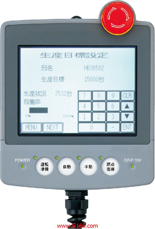
MITSUBISHI A953GOT-LBD-M3-H MITSUBISHI A953GOT-LBD-M3-H

SI-200/250 fiber optic cable.
Double loop.
Remote station.
According to the control requirements of the system, using the appropriate design method to design MITSUBISHI PLC program.
Procedures to meet the requirements of system control as the main line,
Write one by one to achieve the control function or the sub task of the program,
Gradually imprrove the functions specified by the system A953GOT-LBD-M3-H.
MITSUBISHI PLC initialization procedure. After MITSUBISHI PLC on power, the general need to do some of the initial operation,
In order to start making necessary preparations, to avoid the wrong operation of the system A953GOT-LBD-M3-H.
The main contents of the initialization program are: to some data area, counter and so on,
Data needed to restore some of the data area,
Set or reset some relays,
For some initial state display, etc A953GOT-LBD-M3-H.. Input type: DC input, positive common end.
Input points: 8 points.
Enter the response time: 1.5ms the following.
Rated input voltage / current: DC24V/5mA.
Output form: transistor output, leakage type.
Output points: 8 points MITSUBISHI A953GOT-LBD-M3-H.
OFF leakage current: 0.1mA.
Output protection function: No.
Rated load voltage / current: DC24V/0.5A.
External connection: 3 line /2 line type.
Spring clip terminal.
Do not need to be tightened further or locked with screws, which can reduce the working hours of wiring MITSUBISHI A953GOT-LBD-M3-H.
Using 2 pieces of structure of the terminal units, maintenance can be maintained in the same line under the condition of the replacement module.
When installing the module can choose to use the DIN guide rail or screw mounting.
Can be used for the 3 wire sensor input wiring MITSUBISHI A953GOT-LBD-M3-H.
2 axes.
2 axis linear interpolation.
Control unit: pulse, mm, inch, degree.
Determine the location of the number of data: 400/1 axis.
15 pin connector, 9 pin connected analog voltage output (DC-10-10V).
The working process of the input interface circuit: when the switch is closed, the diode light,
The transistor is then guided to the internal circuit and input signal under the irradiation of the light.
When the switch is off, the diode does not emit light, and the transistor is not on the way. Internal circuit input signal.
It is through the input interface circuit to the external switch signal into PLC internal can accept the digital signal.
PLC selection with the development of PLC technology, more and more types of PLC products,
Function is becoming more and more perfect, and its application is more and more extensive.
Different series of different models of PLC has different performance, applicable occasions also have different emphasis,
Price also has a greater difference. Therefore PLC selection,
Under the premise of meeting the control requirements,
Should consider the best performance to price ratio, a reasonable choice of PLC.
Input status and input information input from the input interface,
CPU will be stored in the working data memory or in the input image register.
And then combine the data and the program with CPU.
The result is stored in the output image register or the working data memory,
And then output to the output interface, control the external drive.
MITSUBISHI PLC is the main product in the production of MITSUBISHI motor in Dalian.
It uses a kind of programmable memory for its internal storrage procedures,
Execute logic operation, sequence control, timing, counting and arithmetic operations, user oriented instruction,
And through digital or analog input / output control of various types of machinery or production process A953GOT-LBD-M3-H.
