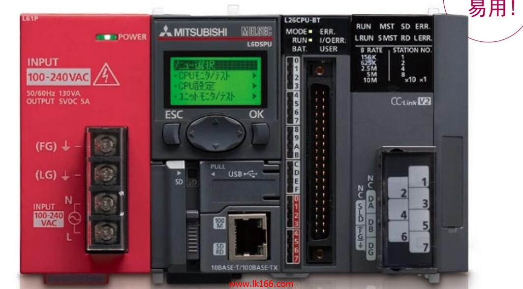
Brand sort
MITSUBISHI FA-TH16YRA20S
MITSUBISHI FA-TH16YRA20S
8 channel.
Input: DC-10~10mA; 0~20mA.
Output (resolution): 0~4000; -4000~4000; 0~12000; -12000~12000; 0~16000; -16000~16000.
Conversion speed: 10ms/ channel.
40 pin connector.
Isolation between channels.
The possibility of expanding control with intelligent function.
At the same time, the channel isolation analog module realizes high isolation voltage,
Further improve the accuracy of the benchmark FA-TH16YRA20S
Provide support for process control using a general purpose programmable controller.
Flow meter, pressure meter, other sensors can be directly connected to analog input,
Control valve can also be directly connected to analog output.
Hardware and installation costs have been greatly reduced due to the need for an external isolation amplifier FA-TH16YRA20S.
High insulation strength.
Can isolate electrical interference, such as current and noise, etc..
Standard analog input module.
Isolated analog input module.
No external isolation amplifier required.
Without the use of inter channel isolation analog modules.
Using the inter channel isolation analog module.A pack of 5 FA-TH16YRA20S.
Applicable models:
AJ65VBTS - - - type .
AJ65VBTCE - - - type.
AJ65VBTCU - - - type.
AJ65ABTP - - - type.
AJ65VBCU- - type.
AJ65SBT-CLB type. The length of the line: 5M.
IP level: IP65.
Direct type.
Bending life: high bending life.
The cable is not shielded.
Electric motor power supply cable for HF-KP/HF-MP series (motor shaft with side extraction). Remote I/O controller, coaxial cable, coaxial loop system.
How to choose MITSUBISHI PLC.
MITSUBISHI PLC options include the choice of MITSUBISHI PLC models, capacity, I/O module, power, etc..
MITSUBISHI PLC distribution I/O points and design MITSUBISHI PLC peripheral hardware circuit
Draw the I/O point of the PLC and the input / output device connection diagram or the corresponding table,
This part also can be caarried out in second stteps FA-TH16YRA20S.
Design PLC peripheral hardware circuit.
Draw the electrical wiring diagram of the other parts of the system,
Including the main circuit and the control circuit does not enter the PLC, etc..
The electrical schematic diagram of the system compooseed of I/O PLC connection diagram and PLC peripheral electrical circuit diagram FA-TH16YRA20S.
So far the system''s hardware electrical circuit has been determined.
FA-TH16YRA20S Operation manual / Instructions / Catalog download link: /searchDownload.html?Search=FA-TH16YRA20S&select=5
...more relevant model market price >>>>
Related products
MITSUBISHI
Terminal module
FA-TH16YRA11
Can e isolated from the output of the p
MITSUBISHI
Terminal module
FA-TH16YRAB20SL
Can e isolated from the output of the p
MITSUBISHI
Terminal module
FA-TH16X200A31
Can e isolated to otain DC24/48/100V,
MITSUBISHI
Terminal module
FA-TH16X100D31L
Can e isolated to otain DC24/48/100V,
Related download


 next one:
  Last one: