Brand sort
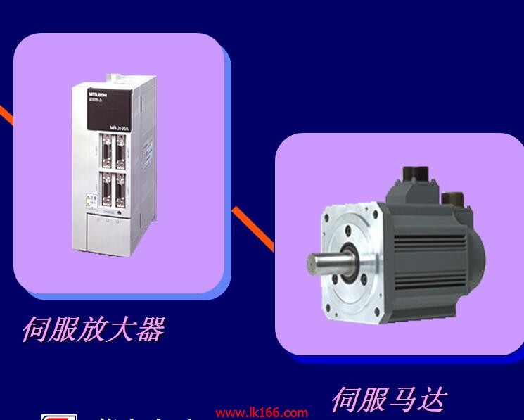
MITSUBISHI MR-J2-10A
Brand:
MITSUBISHI
Country: JAPAN
Name: Universal interface driver
Model: MR-J2-10A
Market price: U.S.$ 1427.12
(The following are the market open price not sales price!)
(The following are the market open price not sales price!)
MITSUBISHI MR-J2-10A
5 slots.
Can be installed in the power supply unit for A series units installed QnA/.
Relay output interface circuit of PLC
Working process: when the internal circuit output digital signal 1,
There is a current flowing through, the relay coil has a current, and then the normally open contact is closed,
Provide load current and voltage .
When the internal circuit outputs a digital signal 0, there is no current flowing through it,
The relay coil does not have a current, and the normally open contact is broken off,
A current or voltage that is disconnected from the load MR-J2-10A
It is through the output interface circuit to the internal digital circuit into a signal to make the load action or not action MR-J2-10A.
I/O points is an important indicator of PLC.
Reasonable selection of I/O points can not only satisfy the control requirements of the system,
And the total investment of the system is the lowest.
The input and output points and types of PLC should be determined according to the analog quantity and switch quantity of the controlled object,
Generally an input / output element to take up an input / output point MR-J2-10A.
Taking into account the future adjustment and expansion,
In general should be estimated on the total number of points plus the amount of spare 20%~30%.
The following describes the centralized control system I/O points of the estimate. MITSUBISHI motor universal AC servo amplifier MELSERVO-J3 series.
Rated output: 0.4kw.
Interface type: SSCNET type III fiber communication.
Special features: integrated driver security.
Power specification: single phase AC200V.
STO function as a security feature is added to the SSCNET III fiber communication type servo amplifier.
By using the STO function, the electromagnetic contactor used in the past to prevent the motor from accidentally starting is no longer needed.
SS1 functions can be realized by using the MR-J3-D05 security logic unit.
MR-J3-BS uses a full closed loop control systtem MR-J2-10A.
Compatibility with MR--J3-B .
MR-J3-BS installation, wiring and connectors are the same as the MR-J3-B, so do not change the existing connection will be easy to MR-J3-B
Change to MR-J3-BS.
Security functions are connected to the CN8 interface through an external securityy ccircuit to increase the MR-J3-BS driver security MR-J2-10A.
Compatible full closed loop control system.
MR-J3-BS has a full closed loop control system version.
MR-J2-10A Operation manual / Instructions / Catalog download link: /searchDownload.html?Search=MR-J2-10A&select=5
...more relevant model market price >>>>
Related products
MITSUBISHI
Personal computer communication cable
MR-J3USBCBL3M
Length: 3 meters.
Purpose: MR-JE-A.
MITSUBISHI
General motors for MR-JE and MR-E
HF-KN13J-S100
Type: HF-KN servo motor, low inertia, lo
MITSUBISHI
Integrated drive safety function driver
MR-J3-200BS
MITSUBISHI motor universal AC servo ampl
MITSUBISHI
Built in positioning function servo amplifier
MR-J2S-200CP
MITSUBISHI general purpose AC servo ampl
Related download


 next one:
  Last one: